Ac To Dc Converter Matlab
You can select different semiconductor types for the HV and LV switching devices. The other two switches are on the output or low-voltage LV side of the converter.

Three Phase Sv Pwm Converter Matlab Simulink
This model variant contains four additional switches that form a full bridge.
Ac to dc converter matlab. Run the command by entering it in the matlab command window. Use the simulation model to size passive components calculate power losses design digital pid controller and implement it on ti tms320f28035. The incorporation of the half bridge non-isolated bidirectional dc-dc converter improves.
VSC1 connected on 60Hz grid is operating as a rectifier. Ac dc converter is simulated with matlab simulink and further verified with 3 0kw experimental prototypes. Both the simulation and experimental results show that the ac dc converter.
The circuit is discretized at. The 600v 60 hz voltage obtained at the secondary of the wye delta transformer is first rectified by a six pulse diode bridge. Controller-driven four quadrant DC-DC.
The full bridge is on the input or high-voltage HV side of the converter. Ac to dc converter matlab simulink simulation complete tutorial duration. For the beginners the definition of AC voltage can be taken as the voltage which changes its direction from positive voltage to negative across same terminal in a specified period of time over and over again.
We can see that the dc voltage drops to 315 v. The IGBT inverter uses Pulse Width Modulation PWM at a 2 kHz carrier frequency. Hi everyone in this video I have demonstrated the simulation of the single-phase ac to dc converter in the Simulink softwareTo get regular updates.
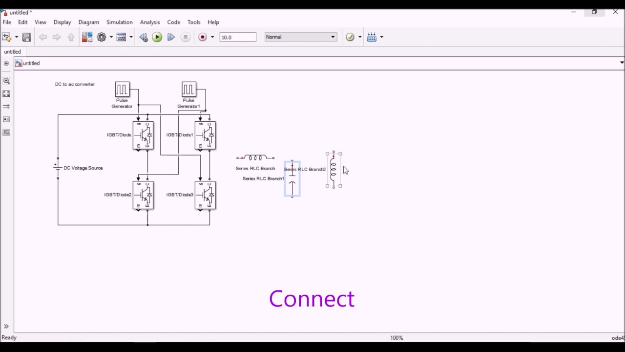
The circuit is discretized at. The basic purpose of an inverter is to convert the Direct Current DC to alternating current AC which is no doubt the opposite of rectifiers. A simple sinusoidal wave is an AC wave.
Dc-ac converter matlab free download. The circuit is discretized at. Controller-driven DC-DC inverting or four-switch step-up or step-down voltage regulator.
For this purpose we will use MATLABSIMULINK and get pulsating DC waveform from AC input. Alternatively the converter can support regenerative power flow from load to supply. The IGBT inverter uses Pulse Width Modulation PWM at a 2 kHz carrier frequency.
This power supply consists of two voltage source converters VSC1 and VSC2 connected through a DC link. The system model has been simulated in the MATLABSIMULINK. A 60 hz voltage source feeds a 50 hz 50 kw load through an ac dc ac converter.
Retrieved August 15 2021. The PWM chopping frequency is 1980 Hz. The filtered DC voltage is applied to an IGBT two-level inverter generating 50 Hz.
Modeling and control of bidirectional DC-DC converter fed PMDC motor for electric vehiclesmodelling and control design for a bidirectional dc-dc converter fed permanent magnet dc PMDC motor traction drive system for EV applications. Ac to dc converter matlab simulink simulation complete tutorial ac to dc converter matlab simulink simulation power electronics ac to dc converter using thyristor single phase ac to dc converter. In this video we will learn how to convert AC supply into DC supply.
A 60 Hz voltage source feeds a 50 Hz 50 kW load through an AC-DC-AC converter. Converter Three-Phase Controller-driven bidirectional ACDC three-arm converter. Isolated converter Bidirectional DC-DC converter with an electrical barrier.
The 600V 60 Hz voltage obtained at the secondary of the WyeDelta transformer is first rectified by a six pulse diode bridge. This video explains about the design and simulation of dc dc converter in boost mode with open loop controls using matlab simulink diamond matlab tutorials. This video explains about the design and simulation of dc dc converter in boost mode with open loop controls using matlab simulink diamond matlab tutorials.
The 600V 60 Hz voltage obtained at the secondary of the WyeDelta transformer is first rectified by a six pulse diode bridge. The filtered DC voltage is applied to an IGBT two-level inverter generating 50 Hz. This power converter regulates voltage on the load side.
A 60 Hz voltage source feeds a 50 Hz 50 kW load through an AC-DC-AC converter. A 60 Hz voltage source feeds a 50 Hz 50 kW load through an AC-DC-AC converter. AC to DC Converter MATLAB Simulink Simulation Complete TutorialAC to DC Converter MATLAB Simulink Simulation Power ElectronicsAC to DC Converter using Thyris.
Ac to dc converter matlab. Systems Biology Format Converter The Systems Biology Format Converter SBFC is a Java generic framework aiming to translate any syst. Ac to ac converters.
The dc voltage is back to 500 v within 1 5 cycle and the unity power factor on the ac. The IGBT inverter uses Pulse Width Modulation PWM at a 2 kHz carrier frequency. The filtered DC voltage is applied to an IGBT two-level inverter generating 50 Hz.
Controller driven bidirectional dc dc step up and step down voltage regulator. It regulates the DC link voltage at 680 V and keeps unity power factor on AC grid. Behavioral model of power converter.
About Press Copyright Contact us Creators Advertise Developers Terms Privacy Policy Safety How YouTube works Test new features Press Copyright Contact us Creators. The 600V 60 Hz voltage obtained at the secondary of the WyeDelta transformer is first rectified by a six pulse diode bridge. A 50 kW 380 V 50 Hz load is connected to a 25 kV 60 Hz grid through a AC-DC-AC power supply.

Closed Loop Simulink Model Of Three Phase Ac To Dc Boost Converter With Download Scientific Diagram

Ac Dc Three Level Pwm Converter Matlab Simulink

Ac To Dc Converter In Matlab Simulink Youtube

Akt Simulating Ac To Dc To Ac Pwm Converter

Three Phase Ac Dc Ac Pwm Converter File Exchange Matlab Central

Three Phase 3 Q Ac To Dc Converter Using Thyristor By Matlab Simulation Youtube

Converters Low Power Matlab Simulink
Simulink Diagram Of The Control Of The 3 Phase Ac Dc Converter Download Scientific Diagram

Solar Power Inverter Matlab Simulink

Matlab Simulink Model For Boost Dc Ac Inverter Download Scientific Diagram

Closed Loop Simulink Model Of Three Phase Ac To Dc Boost Converter With Download Scientific Diagram
Dc To Ac Converter Simulation Youtube

Simulink Model Of Ac Dc Conversion System Download Scientific Diagram

Push Pull Dc To Ac Converter File Exchange Matlab Central
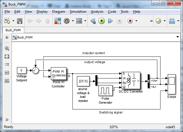
Configurable Simulink Model For Dc Dc Converters With Pwm Pi Control File Exchange Pick Of The Week Matlab Simulink

Ac Dc Ac Converter Matlab Simulink

Bridgeless Ac Dc Boost Converter

Ac To Dc Converter Matlab Simulink Simulation Complete Tutorial Youtube

Power Electronics Matlab Simulink
Post a Comment for "Ac To Dc Converter Matlab"